|
When I received my 720°
the
controller was sluggish and it spun around pretty
roughly and for a short duration, so I proceeded to
rebuild it to make it work as new. It now
spins freely and movement during the game is really
fluid in comparison to how it was before the
rebuild. So as you can see below, the rotary
controller consists of a lot of different parts:
|
The
most common parts that get worn out are the
"pivot ball" and the "roller". In the case
of my controller I also replaced the "lower
ball" as I had it on hand.
You can see these parts listed in the below
diagram for the upper half of the
controller:
|
|

And
for reference, here's the the diagram for
the lower half:
 |
In the below picture, the parts on the left are
the old roller, old pivot ball and old lower ball
that were on my controller, and on the right are new
parts (you can get the roller, pivot ball and lower
ball from
Stephen Beall's site,
www.videogameparts.com):

|
To replace the roller and the pivot ball
you'll need to take the controller apart,
and specifically, you'll need to remove the
pin that keeps the pivot ball in place.
Note that a "bushing" sits inside the pivot
ball.
|
|
The following are
directions about how to replace the roller
and the pivot ball. Thinking about
dismantling this controller and putting it
back together again may seem a bit
overwhelming, but just keep the diagrams
handy (these diagrams are in the manual as
well) and pay attention to what you're doing
and you'll get it done in about 30 minutes
or so.
Start by taking off the "encoder disc
shield" and the "dual optic coupler pcb
assembly". After that, remove the
sprocket assembly (below), clean those parts,
lubricate the sprocket post with white
lithium grease, and put it all back together
and set it aside. |
|
You can now remove the chain and clean and
lubricate it. I twice doused and wiped down
the chain with a dual chain cleaner/lube,
and then applied a final dousing after it
was clean and set it aside. The grime
that you see on the towel below all came off
that chain. |
|
 |
|
Now take off the etched encoder
disc/centering disc unit. NOTE:
there's no need to completely disassemble
the disc unit. Leave the 3 screws that
are on the bottom of the centering disc
alone. All you need to do is loosen
the 2 hex screws that keep that whole disc
assembly secured to the shaft. Now if
your discs are bent or damaged, and you want
to replace those, then you would of
course remove the 3 screws underneath the
centering disc.
www.videogameparts.com
has the centering disc as well as the encoder
disc in stock. When handling these
discs be gentle and be careful not to
drop them as
they are very thin and bend pretty
easily.
Ok now you can remove the retaining ring and
washers that keep the "pivot arm" in place,
and remove the hex screws that secure the
bottom housing plate to the bottom housing.
Once that's done you'll most likely be
looking at a pivot ball and a upper housing
that looks like this: |
|
 |
|
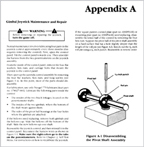
Now it's time to remove the pin keeping the
pivot ball (with bushing) in place. I
placed the free end of the shaft in a small
vise (available at Home Depot, Lowe's,
etc.), and used a small tap and hammer and
eased it out. You can also make your
own device to aid in the pin removal by
getting a small piece of wood and drilling a
hole through out. Refer to Appendix A
below (taken from the Fight Fight manual
whose joystick also utilizes a roll pin):
CLICK IMAGE TO ENLARGE
Once the pin is out, take the
bushing out and clean it. If the
bushing is in too tight you can use the
bottom of a Wico joystick shaft to ease it
out (a tip from Stephen). I used one
of my larger taps and gave it a moderate
push and it came right out. Clean that
bushing, and then put it in your new pivot
ball, and then coat the entire ball with
white lithium grease. Now that the
shaft is free, remove and toss out the old
roller and clean the shaft and both sides of
the upper housing really well. Insert the
new roller and coat it with the grease, and
then coat the lower interior of the upper
housing (just the areas that the roller will
be making contact with). Then put the
shaft back through the housing, insert the
pivot ball (with the bushing inside it) and
align it's holes with the hole on the shaft.
Now place the shaft back in the vise, and
tap in place the pin that keeps the pivot
ball secured: |
|
 |
|
 |
|
Now attach the lower housing to the upper
housing with the 4 long pan-head screws:
|
|
 |
|
If you have a lower ball to replace do
that now. And whether you replace that or
not, you need to lube that part and also
lube the interior of the "pivot arm" hole
(that black piece) with white lithium
grease. Be generous with this grease
and spread a nice thick layer. The
"pivot arm" shaft should be coated with a
light oil like machine tool oil (not 3in1
which is heavier). Secure the pivot
arm and and reassemble the main housing.
Now it's time to put on the disc unit,
chain, and sprocket assembly (it's easiest
to put them on in that order). Screw
in the hex screw that keeps the sprocket
post in place but DO NOT tighten it.
If you tighten it too much, you won't be
able to fine tune the chain and this is
critical for smooth and free rotation of the
controller.
Note the position of the spring pin in the
below picture (the top yellow arrow points to
this). This is a good positioning for the
sprocket at this point. You will notice
some slack in the chain as well (the lower
yellow arrow points to this). |
|
 |
|
Now you can pull the spring pin toward you
but don't make the chain too tight.
You want to leave very slight play in it. |
|
Test the controller now by moving it around
in both directions. If it's not smooth
or if it catches, you have the chain too
tight. When you've got it perfect, now
it's time to tighten the hex screw but again
DO NOT over tighten. If it's too tight
it will keep the sprocket from moving period.
Again, experiment to find the perfect
tension. |
|
Now attach the encoder disc shield and
the dual coupler pcb assembly. There
are two screws securing the coupler
assembly, and you need to find the sweet
spot regarding the positioning of the
bracket. You want them sitting like
this: |
|
NOTE: **If the bracket is aligned too far inward
your discs will rub against the optics.**
You are now finished, congrats on a job well
done.
|
|
 |
|
I made a quick video showing
how smoothly the controller is moving now,
you can check it out here:
http://www.youtube.com/watch?v=Y7iikKiBKRU
FINAL NOTE: There are 2 versions of shafts
and roller configurations existing for this
controller. You may have the earlier
version and if so, please refer to Jeff
Civitate's excellent 720°
Joystick Help page at his site, the
720 Zone:
http://www.720zone.com/720-Joystick-Help.html.
If you do have the earlier version, it's not a problem to use the big
roller in place of that small roller.
The big roller will just sit lower and will
keep itself in place. On the early
version the small roller sits in a notched
area secured by 2 clamps. On the later
version the big roller sits further down and
acts as a dual purpose roller and spacer,
and thus the clamps are not needed.
Also note that your version of the manual
may reflect the early revision shaft. |

HOME

|


